


An equivalent circuit is a theoretical model that exhibits the same voltage, current, and frequency characteristics at its terminals as a more complex, real-world circuit or device. It serves as a simplified representation, making it easier to analyze and predict the behavior of the original system.
For example, the electrical behavior of a DC motor can be modeled by an equivalent circuit combining electrical elements like resistors and inductors. In this model, mechanical properties such as rotational speed and friction are represented by analogous electrical components (e.g., friction is modeled as a resistance). This allows the entire system's characteristics to be analyzed as a purely electrical circuit.
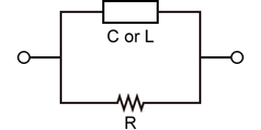
LCR meters utilize equivalent circuit models--typically series or parallel--to calculate and display parameters such as inductance (L), capacitance (C), and resistance (R).
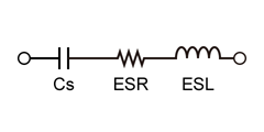
For real-world components like capacitors, equivalent circuits are used to model non-ideal properties. The series equivalent circuit is particularly useful for understanding parasitic effects at high frequencies. This model represents a real capacitor using three ideal components in series:
- Ideal Capacitance (C): Represents the primary, intended capacitance of the component.
- ESR (Equivalent Series Resistance): Represents the resistive losses caused by the capacitor's leads, electrodes, and dielectric material. This resistance generates heat and causes energy loss.
- ESI (Equivalent Series Inductance): Represents the parasitic inductance generated by the leads and internal structure. While negligible at low frequencies, ESI becomes significant at high frequencies, potentially causing the capacitor to exhibit inductive behavior.
The primary advantage of using an equivalent circuit is simplification. By replacing a complex system with a simplified model, engineers can analyze behavior and perform calculations that would otherwise be overly complex or difficult to solve.
Furthermore, this concept extends beyond electronics. Physical phenomena such as mechanical vibration, heat transfer, and acoustics can also be modeled using analogous electrical circuits. This powerful analysis technique is applied in diverse fields, ranging from impedance modeling of biological tissue to the design of mechanical control systems.
Related Technical Articles
- What is a Power Supply? Types and Applications
- What is a Power Supply? (Basic Knowledge)
- Safety and Usage of High Voltage Power Supply
- An Introduction to DC Power Supplies
- What is a Bipolar Power Supply? (Basic Knowledge)
- Electronic Loads: An Introduction to Principles, Types, and Uses
- What is an AC Power Source? - Basic Knowledge -
- Linear vs. Switching Power Supplies: Key Differences Explained
- Types of X-ray Tubes and High-voltage Power Supplies
- High Voltage Measurement Method
- How to Choose a DC Power Supply: Key Points to Consider
- Difference between DC power and AC power
- A Beginner's Guide to Using Power Supplies Safely
- A Guide to Using DC Power Supplies Correctly and Safely
- HVPS for Lab Analyzers: Key Considerations for Stability and Noise
- Amplifier Basics: Principles, Operation, and Key Considerations
- Method of Generating Direct Current (DC) Power